Modules were completed at Pearson's physics module website for section 20.2. The following are screenshots of corresponding answers and models.
20.2
 |
| Answers to questions 1-4. |
 | |
| Answer to questions 5-10. |
 |
| Simulation used for 20.2 |
Modules were completed at Pearson's physics module website for section 20.2. The following are screenshots of corresponding answers and models.
20.2
|
| Answers to questions 1-4. |
| |
| Answer to questions 5-10. |
|
| Simulation used for 20.2 |
Modules were completed at Pearson's physics module website for sections 17.1 and 17.2. The following are screenshots of corresponding answers and models.
17.1
 |
| Answers to 17.1 |
 |
| Answers to 17.1 continued. |
 |
| Screen shot of light clock model. |
 |
| Answers to 17.2 |
 |
| Screen shot of length dilation model. |
These are a series of programs that model solar cell reaction (current over power incident on the surface of the cell) vs. wavelength. The three different models fall into separate categories. The first category, completely theoretical, depicts a model solely based off of mathematical predictions. The second model, for manufactured cells, depicts what the reaction of manufactured silicon cells are. The third model, derived from our data, shows the reaction our cells had.
Completely Theoretical:
 |
| Picture of Graph for response vs wavelength. Units are in I/W and nm. |
 |
| Picture of code from the above model. |
 |
| Picture of Graph for response vs wavelength. Units are in I/W and nm. |
 |
| Picture of code from the above model. |
 |
| Picture of code from the above model. |
 |
| Picture of code from the above model. |
 |
| Picture of code from the above model. |
 |
| Picture of Graph for response vs wavelength. Units are in I/W and nm. |
 |
| Picture of code from the above model. |
With a monochromatic light source and a CD it is possible to create a diffraction pattern. If a diffraction pattern is created from incident light on a CD surface, then the groove thickness in the CD can be measured. In this lab a red laser and a CD was used to create a diffraction pattern. By projecting the pattern on to a screen and measuring the appropriate geometry, the value of groove thickness was obtained.
 | ||
| Image of CD surface depicting grooves and pits. |
 |
| Diffraction in action! Neat! |
 |
| Diffraction pattern created by CD. |
 |
| The dots on the whiteboard correspond to intensity maxima. The order of the maxima are denoted and the geometry used is show in the triangle. |

The purpose of this lab is to measure the thickness of a human hair in two different ways then compare the values. The first method of measuring the human hair will involve treating the human hair like a double slit screen that produces light interference. The second method will involve a traveling microscope: this method will be used to compare the thickness from method one.
The setup involved using a red laser that was incident directly on a taut human hair. A screen was placed several meters away from the hair. The result was a pattern of light and dark fringes. By using the equation

 | |||
| The bright and dark fringes projected onto the screen. |
 |
| Fringe pattern denoted by dots followed with measurements |
This lab consist of creating a real image from a lens and a object projection. By adjusting distances for the object to the lens, a relationship can be studied between image distance, focal length, object distance and magnification.
The setup consisted of a paper screen, a light source, a ring stand, a clamp, a magnifying glass, a screen, and a meter stick. The light source was used to project an image through the magnifying glass (lens) and an then the screen was used to display the resulting image. By adjusting where the magnifying glass was, the object distance, image distance and image height could be changed.
 | |
| The object screen and light source used as a makeshift projector. |
 |
| Object image on the screen resulting from the lens converging light rays. |
| Object Distance (cm) | Image Distance (cm) |
| 130 | 31.8 |
| 104 | 33.4 |
| 78 | 38.4 |
| 52 | 50.6 |
| 39 | 64 |
| Object Height (cm) | Image Height (cm) | Magnification | Type of Image |
| 3.3 | 0.85 | 0.24 | Real/Inv |
| 3.3 | 0.9 | 0.27 | Real/Inv |
| 3.3 | 1.5 | 0.45 | Real/Inv |
| 3.3 | 3.25 | 0.98 | Real/Inv |
| 3.3 | 6.3 | 1.9 | Real/Inv |


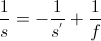
The purpose of this lab is to explore the properties of convex and concave mirrors. This lab will consist of observing an object in either a convex or concave mirror; then, the object will be moved from it's original position and resulting in a change in the image of the object in the mirror.
 | ||
| Image of my hand holding a nail in a convex mirror. |